IBTS Module Upgrade Guide
The IBTS Module Upgrade Guide is made for users upgrading from the V1 IR Sensor, but it also serves as an IBTS Module replacement guide. Skip to IBTS Module Replacement Guide if you're only replacing the IBTS Module.
Choosing The IBTS Module Set Version
The IBTS Module Set is available in two Versions: V1 and V2. The list below describes the suitable versions for each Bullets:
V1:
- V1 Bullets upgrading from IR Sensor.
- V1.5 Bullets using the V1 Control PCB Module.
V2:
- Any V2 Bullets requiring a replacement.
The main difference is the IBTS Cable; the IBTS Module Set V1 includes a V1 IBTS Cable, while the IBTS Module Set V2 includes a V2 IBTS Cable. You can check the difference between the two cables by looking through the document.
Control PCB Module Versions
The Control PCB Module has 4 different versions:
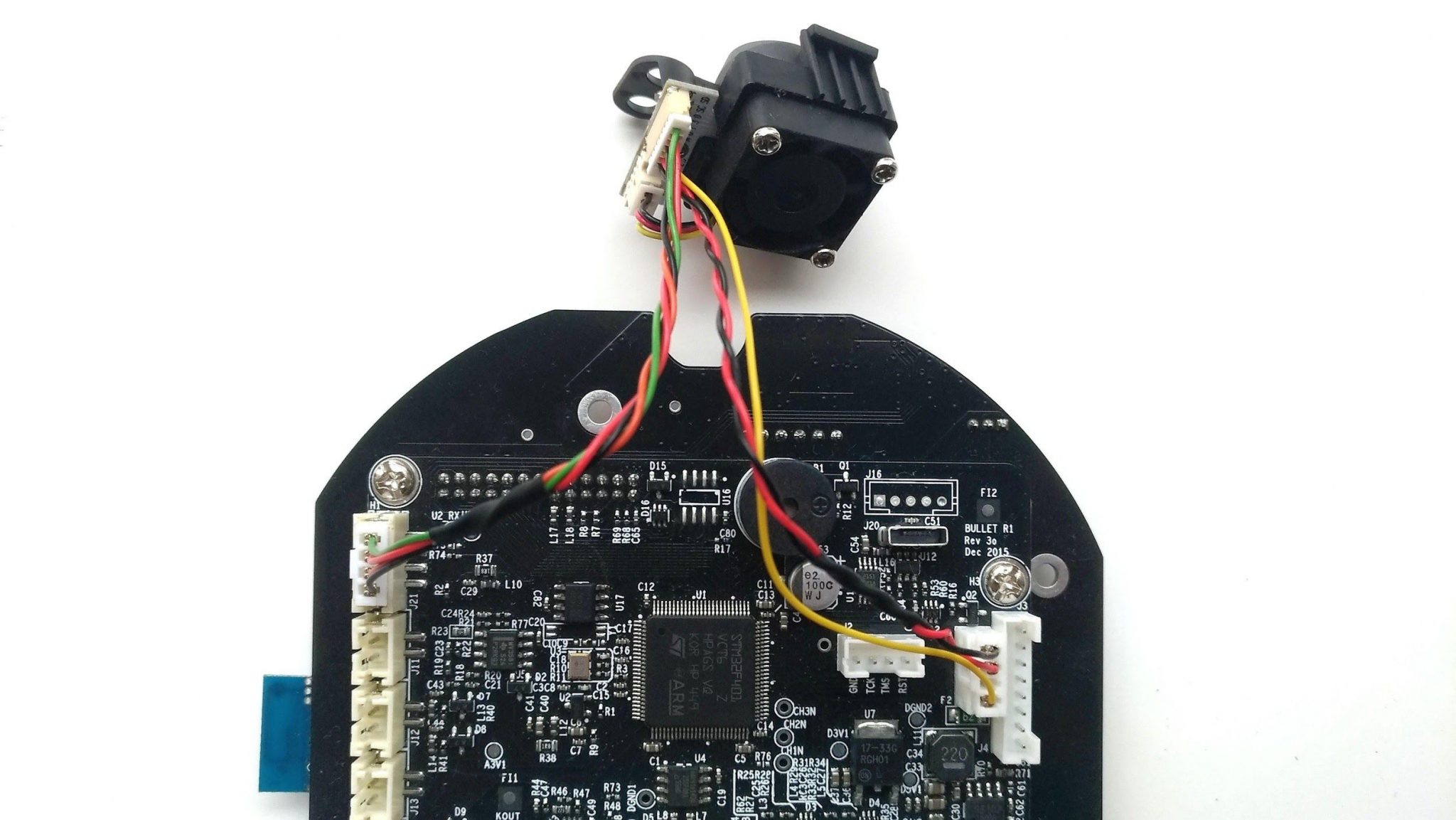
Original Version (V1, 2015)
The original Control PCB Module uses a 4-pin connector to connect the IBTS Module. You will need to purchase an IBTS Module with a V1 IBTS Cable for this version.
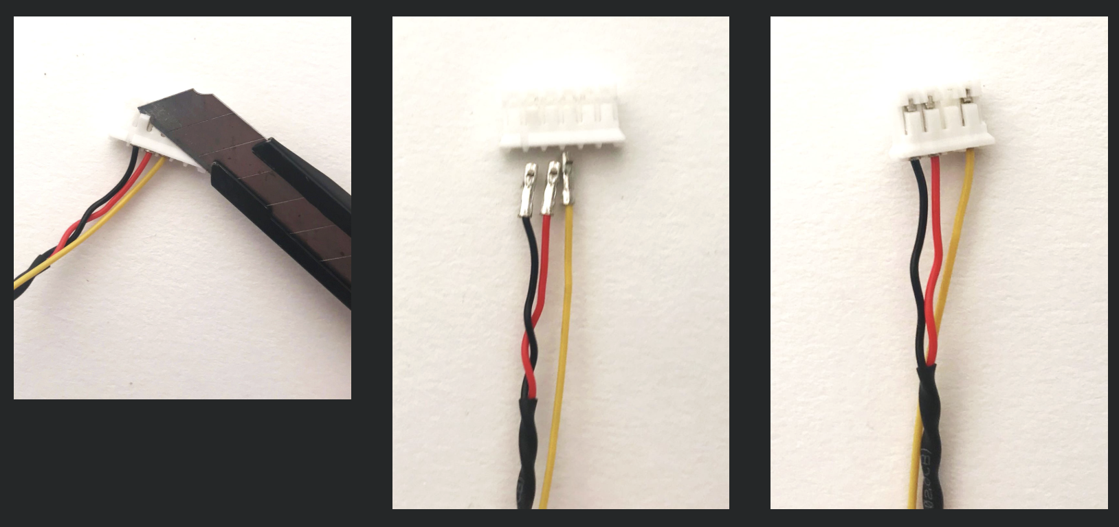
A modification on the IBTS Cable is required for this version. Follow the guide below to modify the V1 IBTS Cable with the included 4-pin female connector:
- Use a Box cutter or a flathead Screwdriver to flip the stopper holding the pins, as illustrated in the lower left.
- Once the wires are removed, install the wires to the 4-pin female connector, as illsutrated in the lower right.
- Push the wires until you feel a click.
- Install the IBTS Cable as shown above.
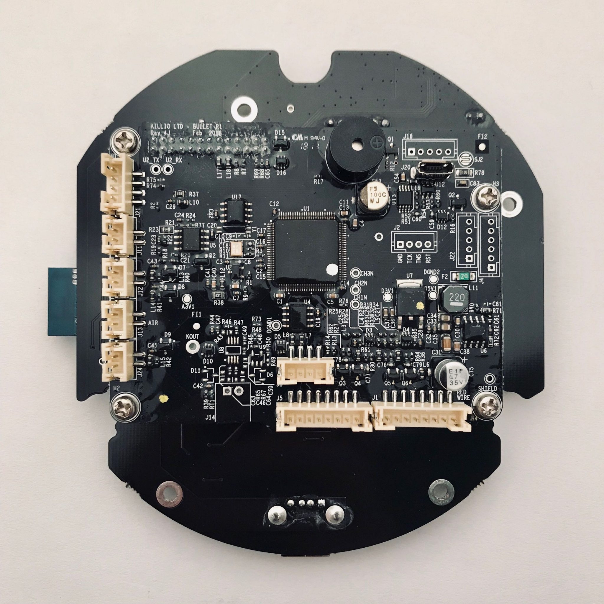
Second Version (V1, 2018)
The second version of Control PCB Module doesn't have a connector on the top right, illustrated below. You will need to purchase an IBTS Module with a V1 IBTS Cable for this version.
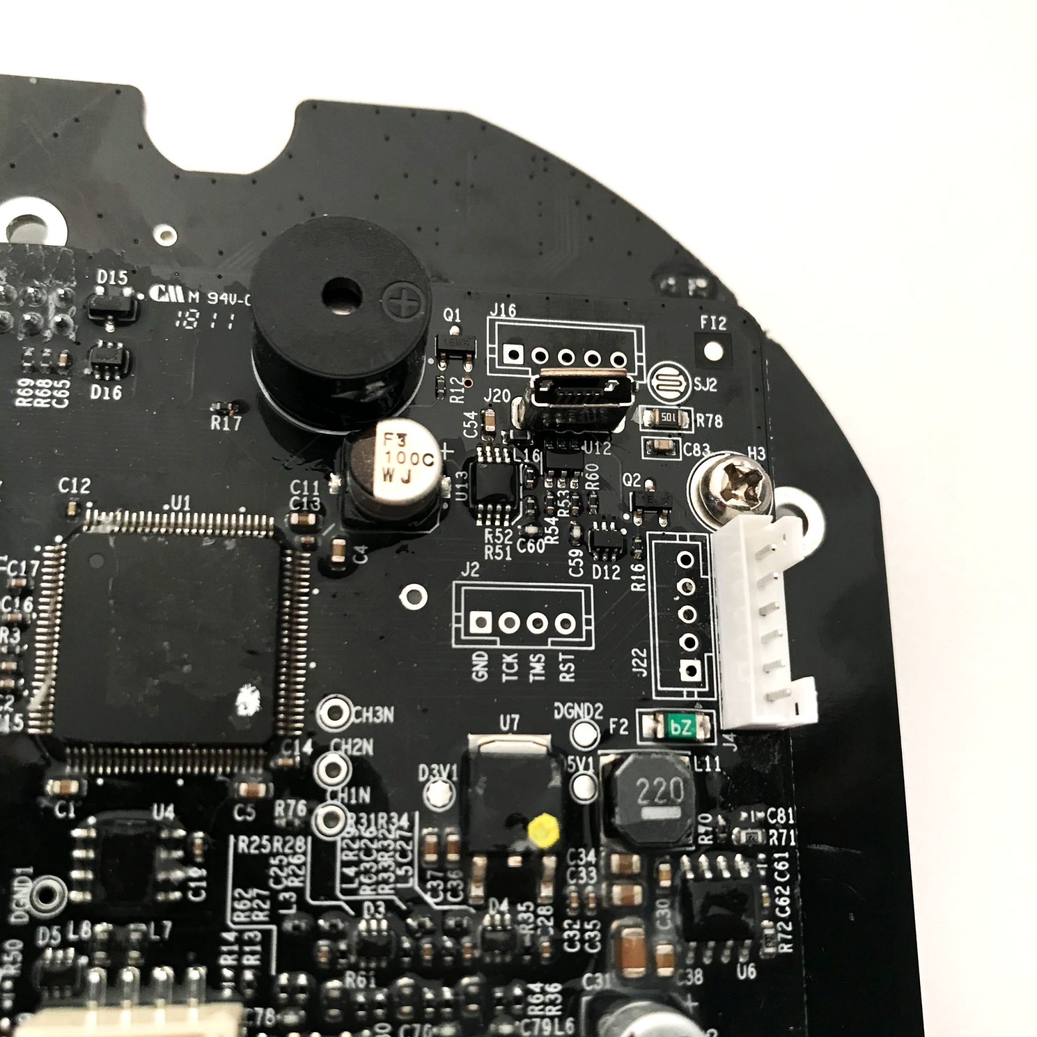
This version requires you to solder a male connector to the Control PCB Module. If you are not confident in your soldering skills, you may find someone skilled to help you out. Follow the guide below to install the 6-pin male connector (included in the IBTS Module kit):
- Remove the four screws (Phillips) holding the Control PCB Module and take it apart.
- Mind the orientation of the 6-pin male connector and solder it onto the Control PCB Module.
You might need to clean up the solder pads a bit, as they might be covered with protective coating.
- Reassemble the Control PCB Module.
- Connect the IBTS Module to the Control PCB Module, as shown above.
The correct orientation for the 6-pin male connector is shown below:
You can follow the video guide below if you are unsure of what to do:
Third Version (V1, 2018)
The third version of Control PCB Module already has the 6-pin male connector, as shown below. You will need to purchase an IBTS Module with a V1 IBTS Cable for this version.

The third version doesn't require any modifications; just install the IBTS Cable as shown above.
Final Version (V2, 2019)
The final version of the Control PCB Module uses a different kind of 7-pin male connector, as shown below. You will need to purchase an IBTS Module with a V2 IBTS Cable for this version.
The final version doesn't require any modifications; just install the V2 IBTS Cable, as shown above.
IBTS Module Installation Guide
The IBTS Fan is delicate. Please don't apply any force on the blade, and only grab it by the outer frame.
A Front Plate disassembly is required for the IBTS Module installation. We recommend you take as many pictures as needed during the disassembly for later reference when putting it back together.
Remove The Control PCB Module
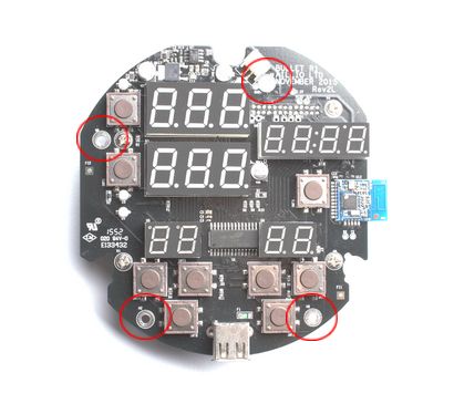
- Remove the three screws (H2) holding the Control Panel.
- Unplug the Speaker Cable.
- Remove the Rubber Buttons.
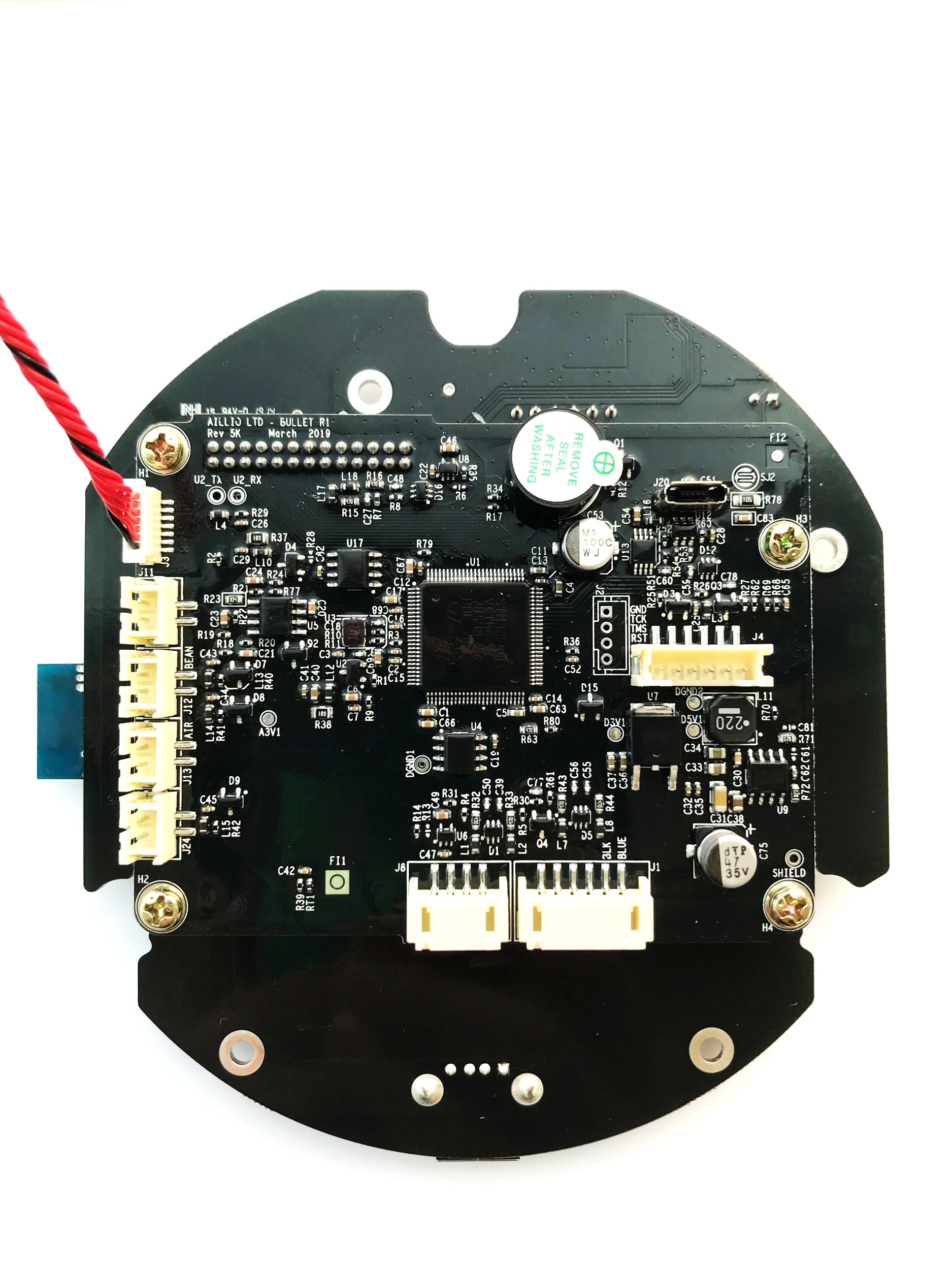
- Remove the four black screws (Phillips) as illustrated in Image 1.
- Unplug all the connectors at the back of the Control PCB Module.
Image 1
Take Out The Front Plate
- Remove the six screws (H3) surrounding the Front Plate, as illustrated in Image 2.
- Remove the four screws (H2.5) holding the Control Housing.
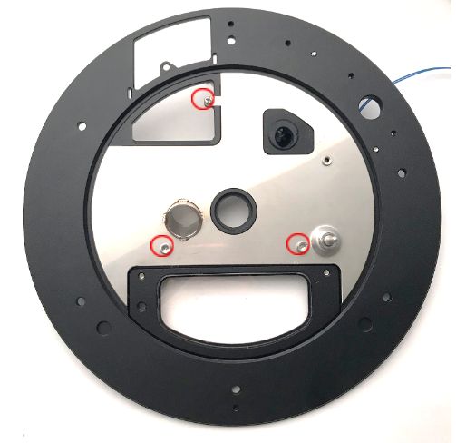
- Remove the Door Hinge Screws (H3) and the screw (H2) on the top, as illustrated in Image 3.
- Take out the Metal Insert.
- Remove the IBTS/IR Sensor Base (rubber) from the Front Plate.
Image 2
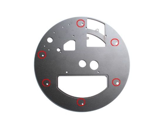
Image 3
IBTS Module Installation
Once you have removed everything from the Front Plate, you can start installing the IBTS Module.
Insert the Rubber Base onto the Fornt Plate, as shown in Image 4.
Image 4
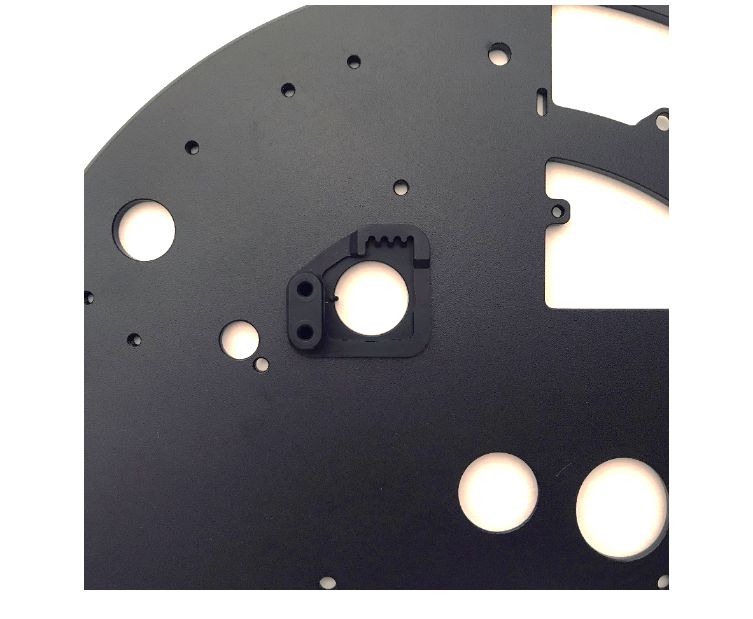
Check if the Rubber Base is fully embedded. The Rubber Base should look flat on both sides, as shown in Image 5.
Image 5
Follow the Image 6 to install the IBTS Eye. Make sure that the cutout on the IBTS Eye matches the stud on the Rubber Base perfectly.
Image 6
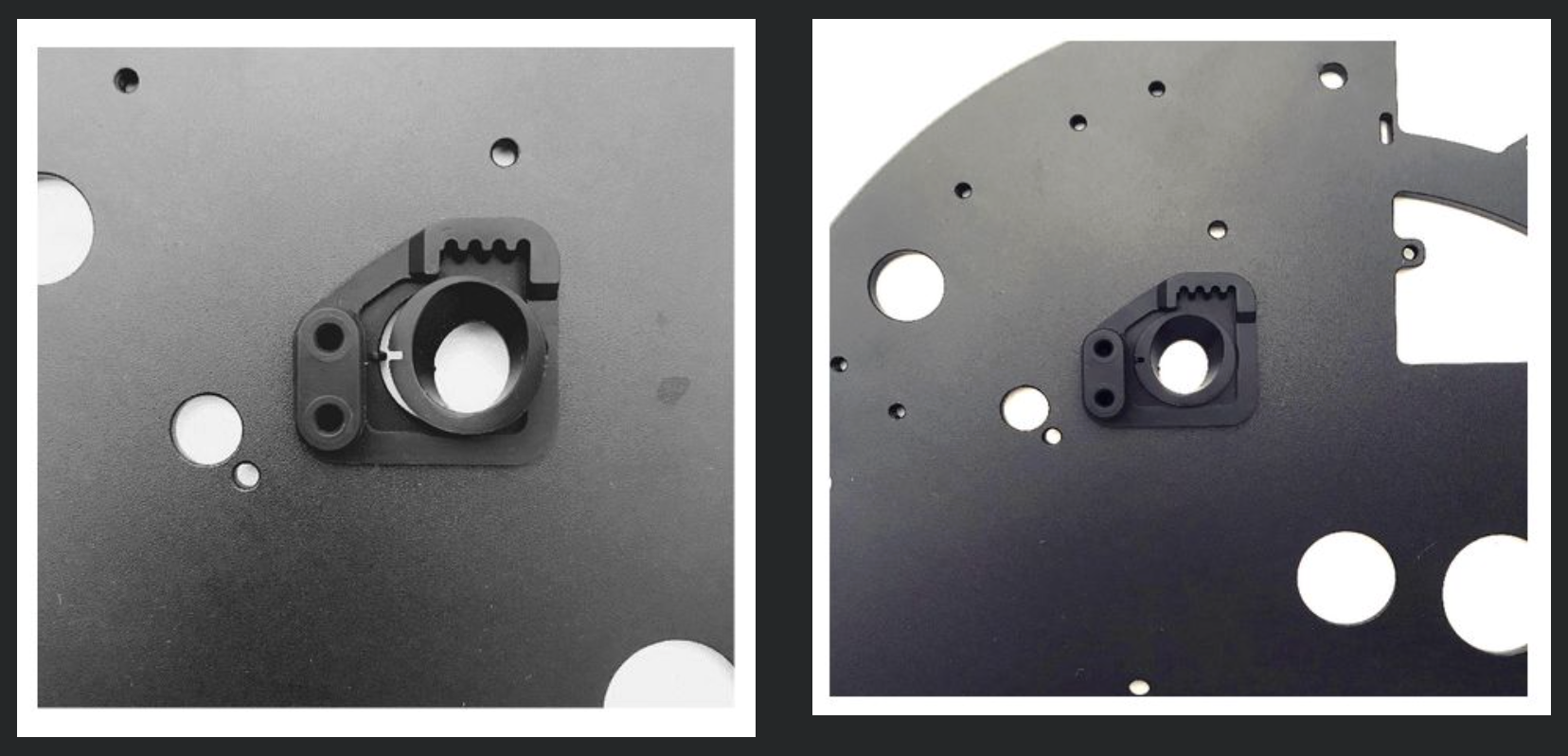
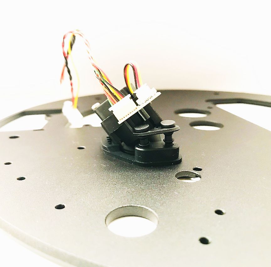
Fit the top grooves on the IBTS Module into the Rubber Base, as shown in the Image 7.
Image 7
Press the two black pins to secure the IBTS Module, as shown in the Image 8.
Image 8
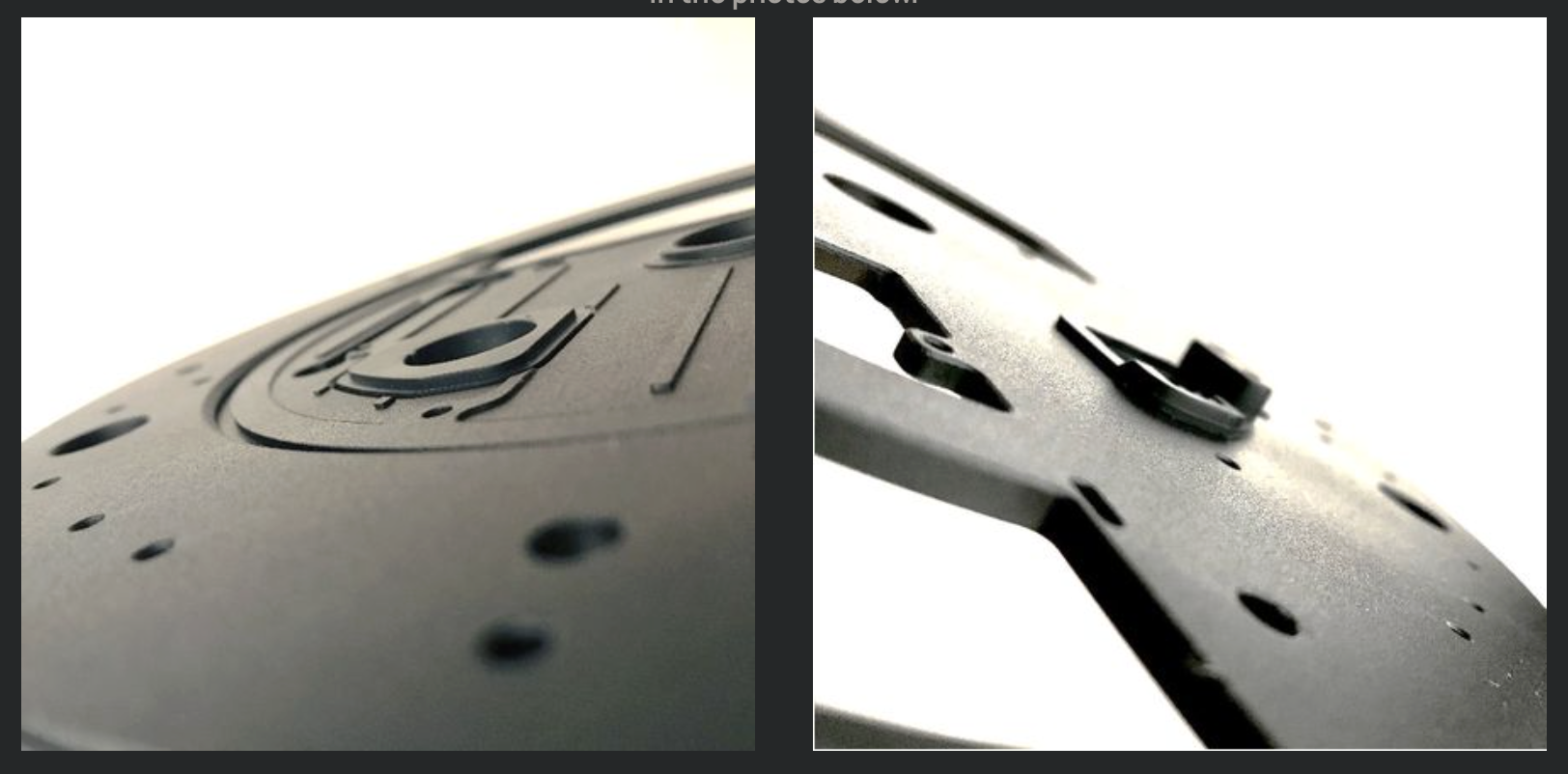
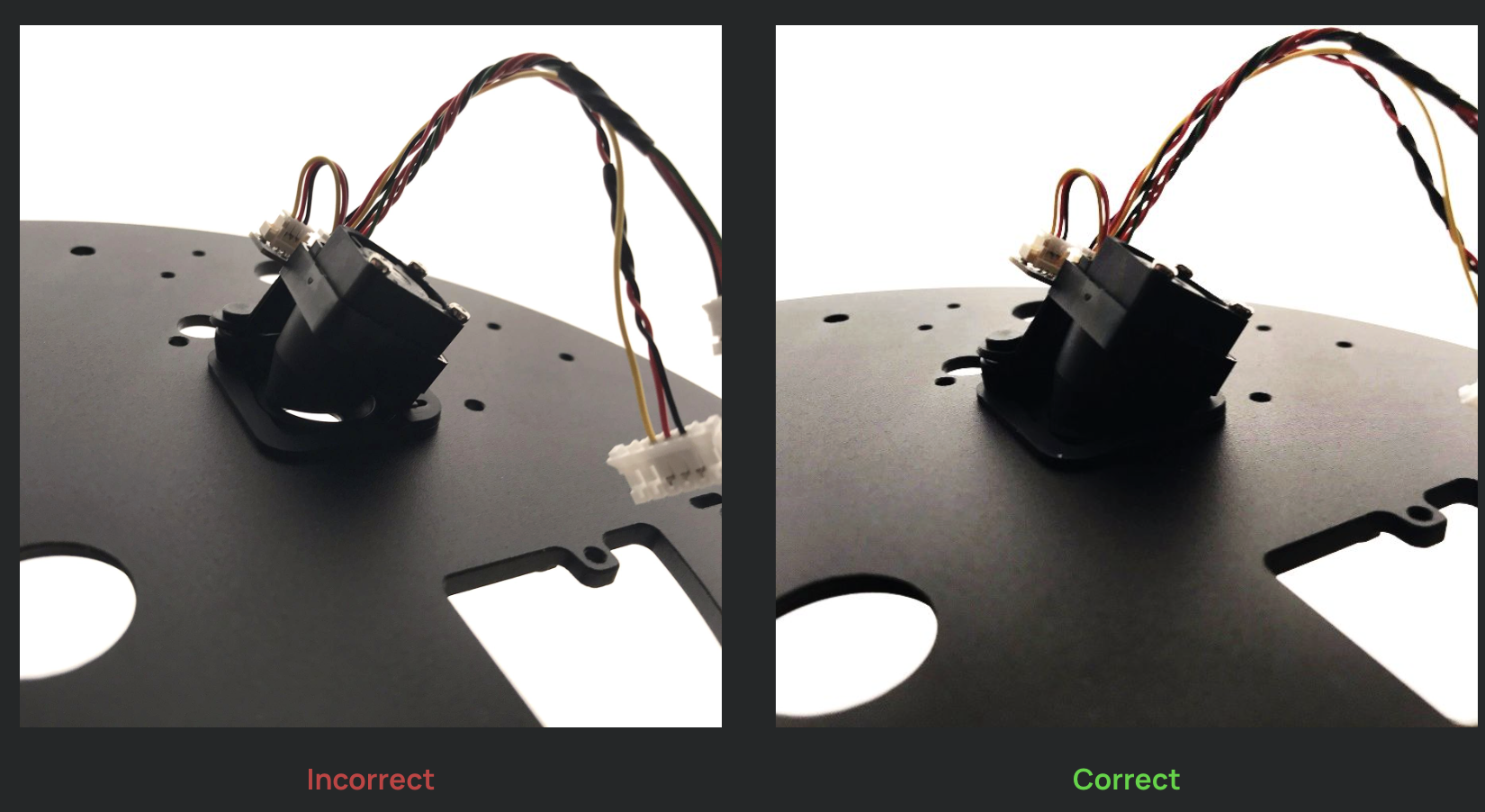
Make sure that there's no gap between the Rubber Base and the IBTS Lens Hood. A gap can cause inaccurate readings, as well as a more frequent maintenance requirement. See Image 9, on the left, is an incorrect installation. Under the light it should instead look like the picture on the right.
Image 9
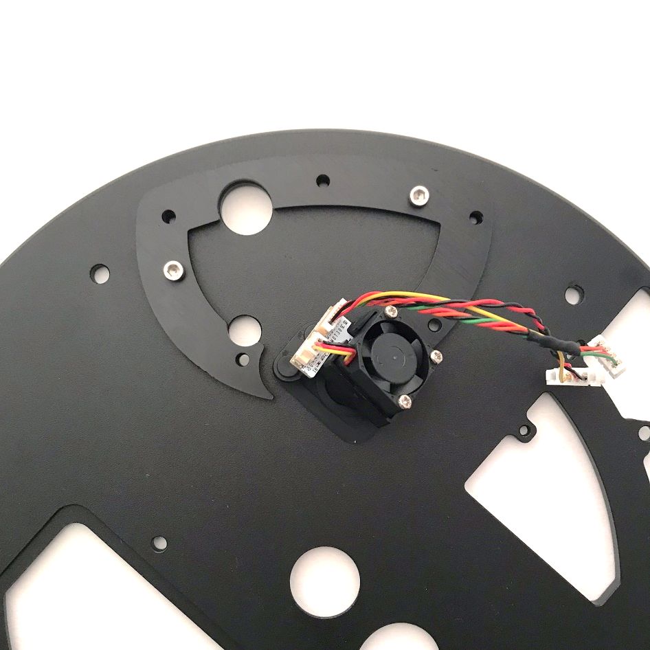
Install the IBTS Bracket, as shown in Image 10. If you find a second, smaller Bracket, install that as well.
Image 10
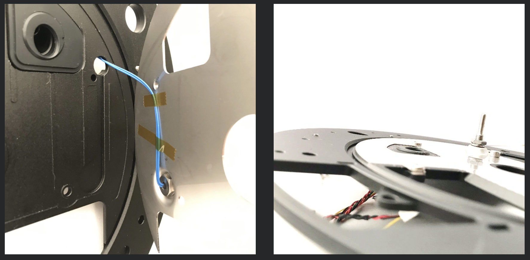
While installing the Metal Insert, make sure that the Bean Probe wire isn't crimped between the Metal Insert and Front Plate, as shown in Image 11. You shouldn't see any gap between the Metal Insert and Front Plate.
Image 11
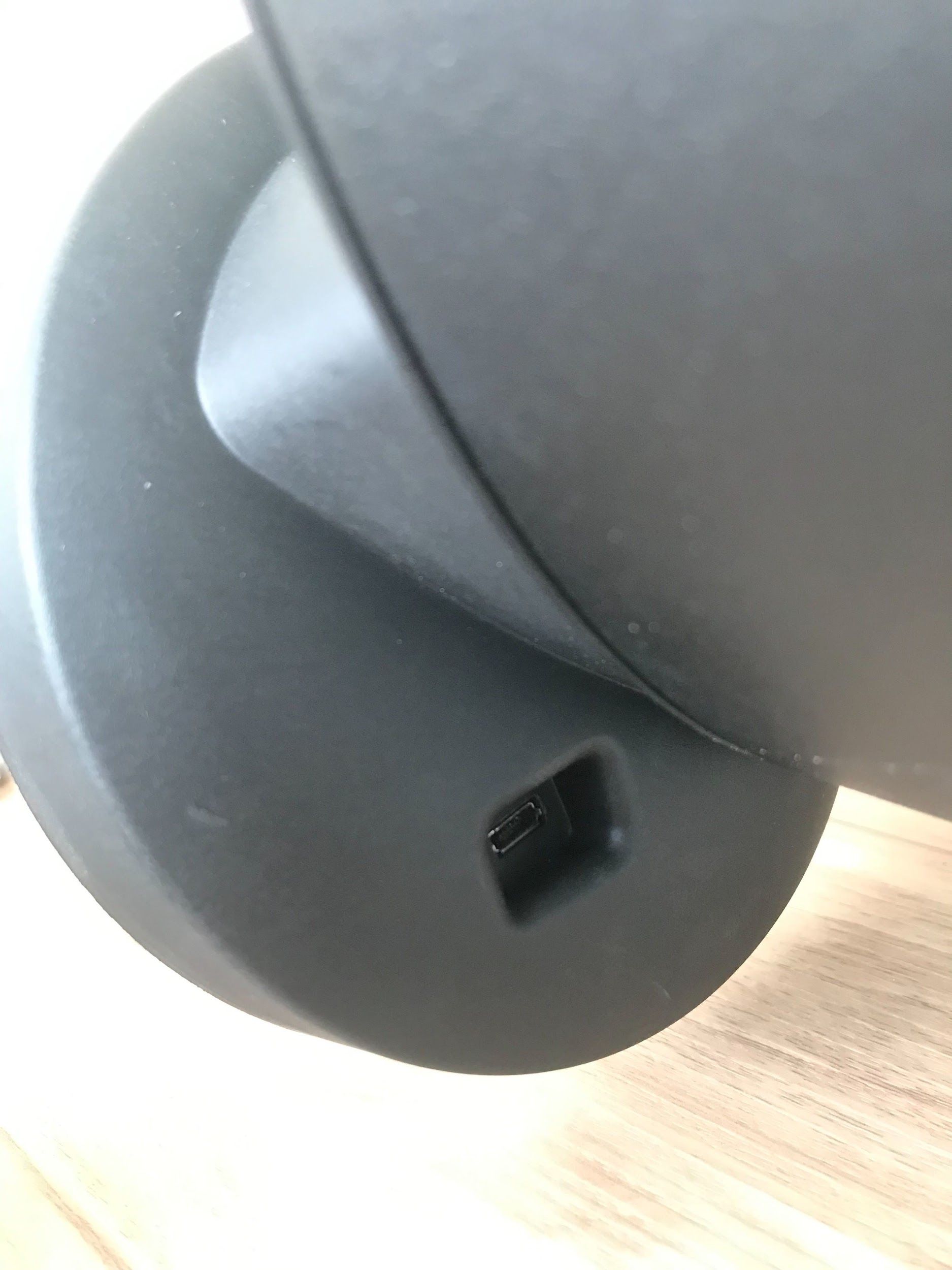
Please make sure that the USB Port is properly inserted into the Control Housing before installing the Control Housing Screws.
After you have installed the IBTS, you will need to update your firmware before you can begin roasting. Please read our IBTS Introduction and QuickGuide, which also contains important information about preheat settings.
If you have any questions, please don’t hesitate to contact us: [email protected]